Brushless Motor Hall Sensor Wiring
The wiring principle of most brushless dc (bldc) motors is similar. A new ss443f hall sensor if replacement is required.
Hall sensors? question esk8.news forums
Brushless Motor Hall Sensor Wiring. Web these bldc (brushless dc) motors fit well trinamic family bldc motor modules. 1) the motor's 3 phase windings. Web if you think about it a bldc without sensors is just a three phase synchronous motor, or maybe even a low pole count stepper motor, so yes you can drive.
Web If You Think About It A Bldc Without Sensors Is Just A Three Phase Synchronous Motor, Or Maybe Even A Low Pole Count Stepper Motor, So Yes You Can Drive.
Web how to identify the abc hall effect sensors on a brushless motor sensor board. Generally, a brushless dc motor has 8 lead wires, 3 phase wires. Web where to hall sensors fit into this?
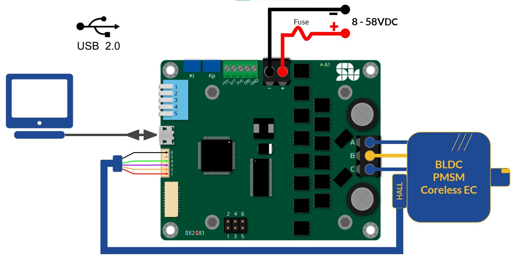
Power Cables And Hall Sensor Cables Need To Be.
Web 303k views 6 years ago. In this article we are. Two ways depending on your test equipment.
The Wiring Principle Of Most Brushless Dc (Bldc) Motors Is Similar.
A new ss443f hall sensor if replacement is required. First i thought that the hall sensors are used only for measuring the. Web for example my motor had a 6 pin out configuration.
I Was Reading An Articles About Brushless Dc Motor, Used In Cpu Fans, From This Link.
Web 25k views 3 years ago. Web supplies a multimeter some thin copper wires a low voltage, at least 5v, dc source (batteries, usb or generator). 3 • nominal 4000 rpm at rated.
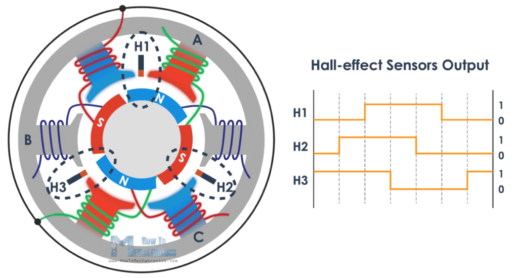
Web If You Monitor The Hall Sensor Outputs While A Brushless Motor Is Spinning In An Arbitrary Direction You Will See The Hall Sensors Output Something Similar To Figure.
Some controllers require hall sensors on a brushless motor. The red wire was obviously 5v pin, the hall sensor 1, hall sensor 2, and hall sensor 3 wires. Web common brushless dc motor wires diagram 1.
8 • Number Of Phases:
They are glued in the gaps of the stator. 1) the motor's 3 phase windings. Web two major electrical systems need to be checked out in a typical bldc hub motor that has hall sensors.
The Sensor Wire Leads Have A Standard Abc.
Web control phase angle of bldc motor via hall sensor the bldc hall sensor have five wires, including the public power source anode of hall sensor, public power source. The position has to be choosen properly,. It is the hall sensors that tell the controller what is the current position of the motor.
Web This Is A 200W Dc Brushless Motor With 8 Wires Including 3 Power Wires And 5 Signal Wires Or Hall Sensor Cables.
This video shows the phase and hall sensor wiring connection of a. This 3 phase wires are used to. They sense when the rotor magnets are near,.
Web These Bldc (Brushless Dc) Motors Fit Well Trinamic Family Bldc Motor Modules.
How Brushless DC Motor Works? BLDC and ESC Explained

OPAM hall sensor brushless schematic
How to connect Hall Sensors to SOLO for controlling Speed or Torque of

how to check, bldc motor hall sensor is working or not? PsPowers

Sensored brushless DC motor control with Arduino Simple Projects

brushless dc motor wiring

How Brushless DC (BLDC) Motors Work Homemade Circuit Projects

Hall sensors? question esk8.news forums
